This document is provided for informational purposes as Mira Pro UE was discontinued several years ago.
Toolbars and Menus
Toolbars now offer the following features:
 Toolbars can be oriented vertically as well as horizontally.
To move a toolbar to a different window border, grab the toolbar's "grip" and drag
it to the new border. The picture at right identifies the toolbars and
their features. The toolbars are shown docked
vertically along
the left main window border.
Toolbars can be oriented vertically as well as horizontally.
To move a toolbar to a different window border, grab the toolbar's "grip" and drag
it to the new border. The picture at right identifies the toolbars and
their features. The toolbars are shown docked
vertically along
the left main window border.
To configure or reset toolbar buttons, click the small down-arrow at the right or bottom end of the toolbar.
Several toolbar buttons now have down-arrows to open a menu of additional functions.
Fine positioning of a toolbar among other toolbars along a border is most easily done using two steps:
- Move the toolbar to the new border and dock it there. Release the mouse button.
- Re-grip the toolbar and then finely position the toolbar relative to other toolbars.
The toolbar layout is remembered between Mira sessions.
Docking Panes
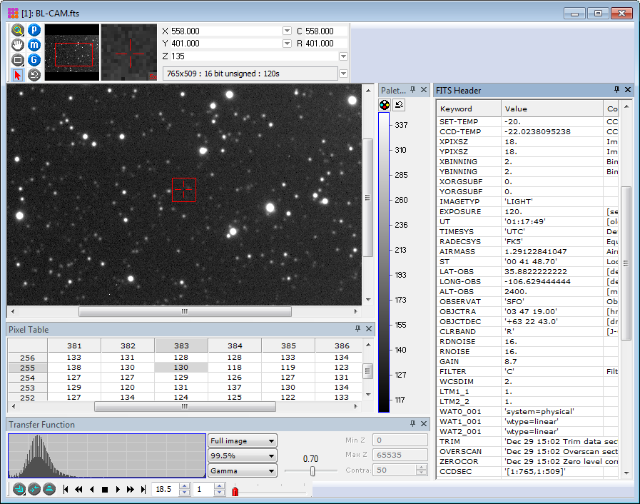 Docking panes are now used for several Image window commands. Panes are provided
for the Transfer Function, Palette Adjustment, FITS Header, and Pixel Table.
In the picture at right, all but the FITS Header pane are shown docked on their
Image Window border. Each pane is described below.
Docking panes are now used for several Image window commands. Panes are provided
for the Transfer Function, Palette Adjustment, FITS Header, and Pixel Table.
In the picture at right, all but the FITS Header pane are shown docked on their
Image Window border. Each pane is described below.
Docking Panes are opened and closed by toggling their button on a toolbar. Pane buttons are indicated by a rectangular outline on the icon. Buttons on the docking panes allow them to be closed, aligned to a different window border, or shrunk to a tab. You also can drag them away from the window to float on the desktop.
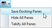 The Docking Pane layout for a given window type can be saved or modified using
the Docking Pane toolbar button or commands in the View > Docking Panes menu.
The toolbar button and its drop menu are shown at right.
The button saves the layout. The drop button offers additional commands.
The Docking Pane layout for a given window type can be saved or modified using
the Docking Pane toolbar button or commands in the View > Docking Panes menu.
The toolbar button and its drop menu are shown at right.
The button saves the layout. The drop button offers additional commands.
![]() Pixel Table Pane: This pane shows pixel values
near the location of the image cursor. With the Pixel Table open, the pixel
values track the image cursor as it moves using the mouse or the arrow keys.
Note that the window must have the keyboard focus to move the cursor using the arrow keys.
To see a menu of Pixel Table commands, right click on the table.
Pixel Table Pane: This pane shows pixel values
near the location of the image cursor. With the Pixel Table open, the pixel
values track the image cursor as it moves using the mouse or the arrow keys.
Note that the window must have the keyboard focus to move the cursor using the arrow keys.
To see a menu of Pixel Table commands, right click on the table.
![]() Palette Adjustment Pane: This pane
provides palette adjustments using the mouse and shows the pixel values assigned
to the palette entries. It is available in both horizontal and vertical
orientations. The vertical version adds a button for resetting the palette and
another button for opening the Palette Manager dialog.
Palette Adjustment Pane: This pane
provides palette adjustments using the mouse and shows the pixel values assigned
to the palette entries. It is available in both horizontal and vertical
orientations. The vertical version adds a button for resetting the palette and
another button for opening the Palette Manager dialog.
- To modify the palette, mouse-down on the color ramp and move the mouse while keeping the left button pressed. Sideways and back-forth movements change brightness and contrast simultaneously.
- To view the pixel values assigned to the grayscale/color palette entry, right mouse-down on the palette and move the mouse along the palette while keeping the right button pressed.
![]() Transfer Function Pane: This pane
provides adjustments to the image transfer function. This pane can be opened in horizontal and vertical
orientations.
Transfer Function Pane: This pane
provides adjustments to the image transfer function. This pane can be opened in horizontal and vertical
orientations.
 FITS Header Pane: This pane shows
the FITS format image header. The pane updates when an operation modifies the
image header.
FITS Header Pane: This pane shows
the FITS format image header. The pane updates when an operation modifies the
image header.
To save the pane layout for future Image windows, use commands from the GUI button on the main toolbar or the View | GUI menu command.
Tear-off Submenus
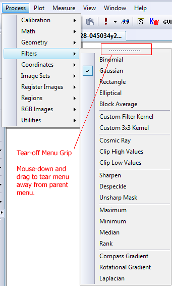 Tear-off menus can be dragged away from their parent menu to provide a Toolbar-like method for accessing commonly used menu commands. Menus
with this feature have a narrow [.......] grip along their top border.
After the tear-away menu separates from its parent, you can dock it as a toolbar
along one of the main window borders.
Tear-off menus can be dragged away from their parent menu to provide a Toolbar-like method for accessing commonly used menu commands. Menus
with this feature have a narrow [.......] grip along their top border.
After the tear-away menu separates from its parent, you can dock it as a toolbar
along one of the main window borders.
To delete a docked tear-off menu, mouse-down on its grip and undock (float) it, then click its [x] button to close the floating menu.
Command Dialogs
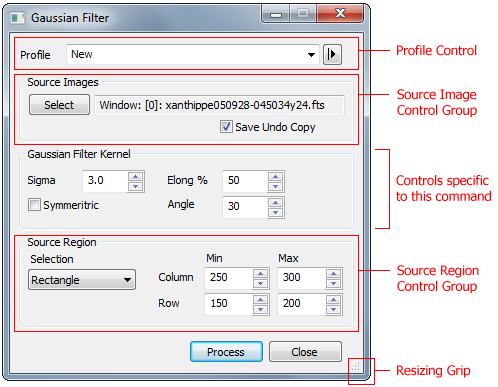 More than 45 commands use new dialogs that provide enhanced capability. These
commands are located in the first 5 submenus under the Process
menu of the top menu bar. The Gaussian Filter dialog shown at
right identifies the new dialog and command features.
More than 45 commands use new dialogs that provide enhanced capability. These
commands are located in the first 5 submenus under the Process
menu of the top menu bar. The Gaussian Filter dialog shown at
right identifies the new dialog and command features.
Source images used by the dialog now can be opened from files as well as displayed images.
Dialogs are now "modeless", meaning that they can remain open while you have access to other aspects of the GUI. They do not lock-out other functionality until you close them.
All dialogs can be resized to allow some of the controls to display more information.
These dialogs are standardized in operation and appearance, and offer new functionality in terms of a Profile Control for parameter selection, a Source Selection Control Group for selecting images, and a Region Control Group for selecting the part of the image to be processed.
Profile Control
![]() In
Mira 8, some 77 command dialogs use a Profile Control to load and save named sets of parameters
used by the dialog.
The profile command is always the top-most item on the dialog. The current profile name is shown in the list box.
The arrow button to the right of the list box has menu commands to save the parameter set, save
it as a new name, delete it, or lock it to prevent accidental changes. To load one of the saved
parameter sets, select its name from the list box. By default, the initial parameter set has the profile name "new".
In
Mira 8, some 77 command dialogs use a Profile Control to load and save named sets of parameters
used by the dialog.
The profile command is always the top-most item on the dialog. The current profile name is shown in the list box.
The arrow button to the right of the list box has menu commands to save the parameter set, save
it as a new name, delete it, or lock it to prevent accidental changes. To load one of the saved
parameter sets, select its name from the list box. By default, the initial parameter set has the profile name "new".
Source images processed by the dialog command are selected using the new Source Images Control Group, as described below.
Source Images Control Group
![]() This group of controls is used to select the source images that will be
processed by the dialog. The group appears immediately below the Profile group
and is outlined with a group box. A few dialogs add a secondary Source Image
group when a second image is required (i.e., the Image Arithmetic,
Imbed Image,
and Normalize Image commands). This tool provides a batch mode
alternative to opening images to the display and is available in 41 different
command dialogs. The Select button opens a selection dialog which
offers 5 options for selecting source images. These range from selecting an open
Image Window to selecting files meeting criteria based on FITS header keyword
values.
This group of controls is used to select the source images that will be
processed by the dialog. The group appears immediately below the Profile group
and is outlined with a group box. A few dialogs add a secondary Source Image
group when a second image is required (i.e., the Image Arithmetic,
Imbed Image,
and Normalize Image commands). This tool provides a batch mode
alternative to opening images to the display and is available in 41 different
command dialogs. The Select button opens a selection dialog which
offers 5 options for selecting source images. These range from selecting an open
Image Window to selecting files meeting criteria based on FITS header keyword
values.
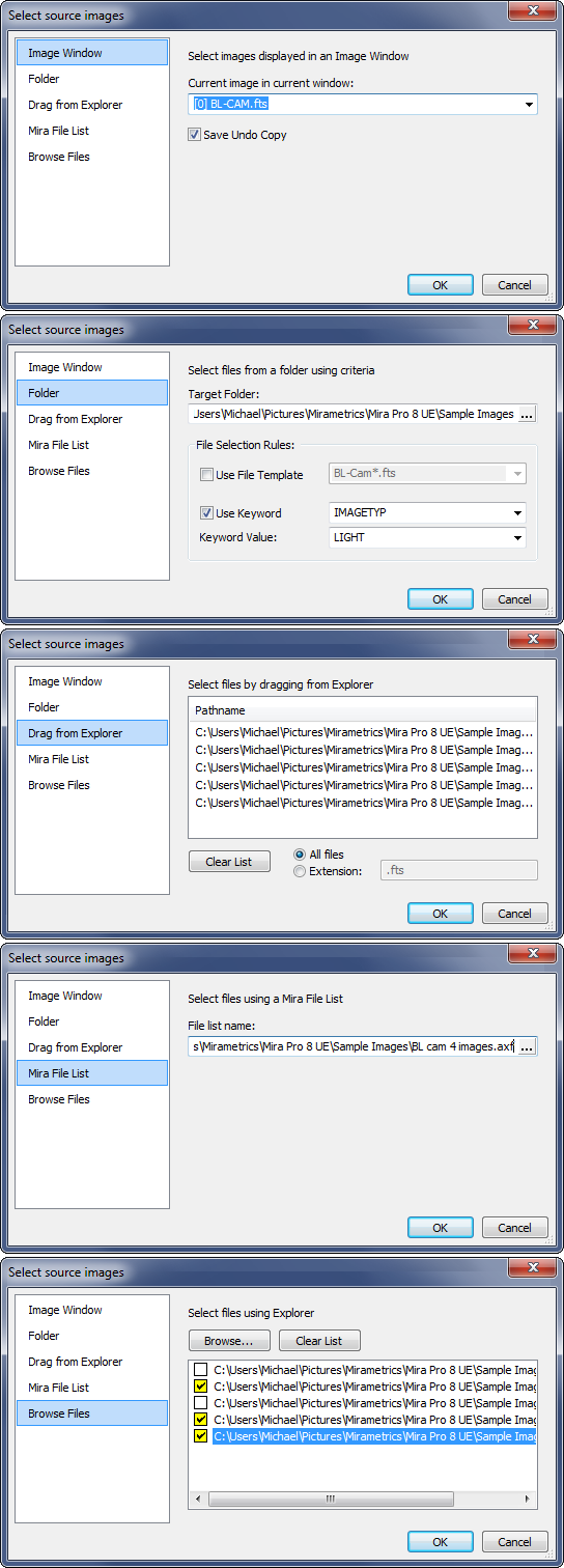 The [Select]
button opens the Select Source Images dialog which offers 5 methods for
selecting target images to be processed. Click the thumbnail image at right to
see all 5 selection dialogs.
The [Select]
button opens the Select Source Images dialog which offers 5 methods for
selecting target images to be processed. Click the thumbnail image at right to
see all 5 selection dialogs.
- Image Window: Source files are taken from the currently selected Image Window. If the window contains an Image Set, then you can elect to process the entire image set or just the top-most image visible in the window. To process the image set, keep the Process Image Set button on the Image Window toolbar set at [P]. To process only the top-most image, toggle the [P] button to its [P1] form. To create an Undo backup copy of displayed images, check the Save Undo Copy box in the Source Images Control Group.
- Folder: Source files are taken from a folder. You can set criteria for file selection based on specific keywords in the FITS image header or using a wildcard file template. If no criteria are selected, then all files in the folder are selected.
- Drag from Explorer: Source files are selected from those dragged from Windows Explorer (the "file manager") and dropped onto the Files field in the selection dialog.
- Mira File List: Source files are opened from files contained in a Mira File List. Simply select the file list and the files will be determined when the command is processed.
- Browse Files: Source files are selected manually using the Windows File Open dialog.
Source Region Control Group
The bottom region of several dialogs includes a Source Region Control Group for selecting a processing rectangle on the source images. This is shown in the diagram of the new Command Dialogs described above.
Image Windows
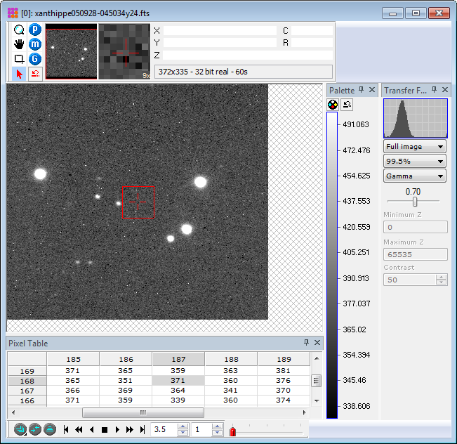 One of the major new user interface changes in version 8 is docking panes which
contain specific types of data related to the host image window.
The Image Window at right shows
several docking panes open at once. You can shrink each of the panes to tabs,
close them, or change their anchor. Their layout can also be saved for future
Image Windows.
One of the major new user interface changes in version 8 is docking panes which
contain specific types of data related to the host image window.
The Image Window at right shows
several docking panes open at once. You can shrink each of the panes to tabs,
close them, or change their anchor. Their layout can also be saved for future
Image Windows.
Palettes
Mira version 8 uses a new palette format which stores palettes in the Windows Registry. As a consequence, the software comes with a relatively small set of palettes in the new native format. However, a large collection of palettes from previous version is included and these can be converted and saved using the View | Palette | Import Palettes command. This command can also be used to import palettes you created in Mira 7. Palettes can be saved to an "old format" file outside the Windows Registry using the View | Palette | Export Palettes command. The new Palette Manager dialog is resizeable
Image window Toolbar
![]() Image
Toolbar: The Image Toolbar layout has been changed. Command
buttons previously located along the horizontal image toolbar border have been
moved onto main toolbars to make room for an image information readout. Also, 4
buttons were added beside the information readouts for configuring the
information display.:
Image
Toolbar: The Image Toolbar layout has been changed. Command
buttons previously located along the horizontal image toolbar border have been
moved onto main toolbars to make room for an image information readout. Also, 4
buttons were added beside the information readouts for configuring the
information display.:
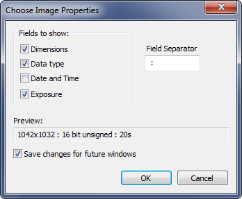 Image Information Readout: This field was added to the toolbar to
show basic information about the currently displayed image. The
information shown in the readout field can be changed using the button beside
the display field. The display is automatically updated when a new image member
is becomes the current image. This dialog is shown at right. Not all items can be displayed in the width of the toolbar field at one
time.
Image Information Readout: This field was added to the toolbar to
show basic information about the currently displayed image. The
information shown in the readout field can be changed using the button beside
the display field. The display is automatically updated when a new image member
is becomes the current image. This dialog is shown at right. Not all items can be displayed in the width of the toolbar field at one
time.
 Changing the
Linear
World Coordinate ("X" and "Y") Format: The
world coordinate fields have been a Mira feature for 2 decades. A new capability
was added for changing the number format shown in the X- and Y-axis world
coordinate readouts when a linear coordinate calibration is used. A linear
calibration might be units of arc seconds or microns per pixel. As shown in the
diagram at right, to change the X-axis format, double-click on the X-Axis world
coordinate readout. To change the Y-axis format, click the button to the right
of the X- or Y-axis readout field. Since the readout is particular to the image
toolbar and the image window, changes are not saved to the image. However, the
dialog gives you several options for saving the format changes for coordinates
displayed in this window or future image windows. Also see the new Set
Coordinate Units command.
Changing the
Linear
World Coordinate ("X" and "Y") Format: The
world coordinate fields have been a Mira feature for 2 decades. A new capability
was added for changing the number format shown in the X- and Y-axis world
coordinate readouts when a linear coordinate calibration is used. A linear
calibration might be units of arc seconds or microns per pixel. As shown in the
diagram at right, to change the X-axis format, double-click on the X-Axis world
coordinate readout. To change the Y-axis format, click the button to the right
of the X- or Y-axis readout field. Since the readout is particular to the image
toolbar and the image window, changes are not saved to the image. However, the
dialog gives you several options for saving the format changes for coordinates
displayed in this window or future image windows. Also see the new Set
Coordinate Units command.
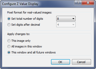 Changing the Pixel Value ("Z") Coordinate Format: The
pixel value format can be changed using the button to the right of the pixel
value readout field. Since the pixel value readout is particular to the image
toolbar and the image window, changes are not saved to the image. However, the
dialog gives you several options for saving the format changes for coordinates
displayed in this window or future image windows.
Changing the Pixel Value ("Z") Coordinate Format: The
pixel value format can be changed using the button to the right of the pixel
value readout field. Since the pixel value readout is particular to the image
toolbar and the image window, changes are not saved to the image. However, the
dialog gives you several options for saving the format changes for coordinates
displayed in this window or future image windows.
Image Set Button State: These 3 buttons on the left end of the Image Toolbar indicate whether the image set or current image will be processed (P), measured (M), or graphed (G). In previous versions, the status for processing 1 image of the image set was not clearly indicated. In version 8, single image mode is indicated with a "1" next to the P, M, or G.
New commands
Commands on the main toolbar
Kwee-van Worden Solver: Computes the time of minimum and uncertainly for the bottom of a light curve using the Kwee-van Worden algorithm. Paste time/magnitude data into the dialog.
Synthetic Image: Creates a synthetic image using all noise components and has an option for adding artificial stars.
File Event Scripting: Executes a Mira script when triggered by a file event in a matched folder. See the extensive description and tutorial in the on-line documentation.
Commands on the Cursor Tools toolbar
This is one of the toolbars that dock with the Mira main frame.
XY button: This button opens the "Go To Cursor Coordinates" command (also available in the "View | Coordinates" menu or using Ctrl+G on the Image Window). Use this dialog to save the image cursor coordinates, to transfer the cursor position between images, send the cursor to manually entered coordinates, or save a coordinate and then later recall it and send the cursor there.
Menu Commands
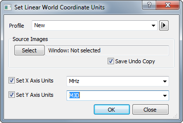 Set Linear World Coordinate Units:
This dialog is used to define coordinate units for a linear world coordinate
calibration. This command is located in the Process | Coordinates
menu. The units will be displayed in the Image Toolbar coordinate readouts
whenever a linear coordinate calibration exists for that image. The Source
Images Control Group defines which images are updated with the specific units.
If a window is selected and the window contains an image set, then the choice
for updating either the entire image set or just the 1 image currently displayed
is handled by the state of the Image Set Processing button (P) on the Image
Toolbar.
Set Linear World Coordinate Units:
This dialog is used to define coordinate units for a linear world coordinate
calibration. This command is located in the Process | Coordinates
menu. The units will be displayed in the Image Toolbar coordinate readouts
whenever a linear coordinate calibration exists for that image. The Source
Images Control Group defines which images are updated with the specific units.
If a window is selected and the window contains an image set, then the choice
for updating either the entire image set or just the 1 image currently displayed
is handled by the state of the Image Set Processing button (P) on the Image
Toolbar.
FITS RGB Image Support
 Mira can open an RGB image stored in a FITS file.
FITS format does not natively support data having a multi-channel pixel type
such as the RGB color images. , Despite that
limitation, RGB images are sometimes stored in FITS files using the 3rd axis
to store 1 plane each for the R, G, and B channels. There is no standard
FITS identifier for such images so Mira implements support through its File
Opening Plug-in Interface. To open a FITS RGB file, use the File | Open method but select
FITS RGB Image from the list of file filters, as shown in
the picture at right. Be careful not to confuse this filter with the
standard FITS file filter, named FITS Images.
Mira can open an RGB image stored in a FITS file.
FITS format does not natively support data having a multi-channel pixel type
such as the RGB color images. , Despite that
limitation, RGB images are sometimes stored in FITS files using the 3rd axis
to store 1 plane each for the R, G, and B channels. There is no standard
FITS identifier for such images so Mira implements support through its File
Opening Plug-in Interface. To open a FITS RGB file, use the File | Open method but select
FITS RGB Image from the list of file filters, as shown in
the picture at right. Be careful not to confuse this filter with the
standard FITS file filter, named FITS Images.