Bias Correction Properties
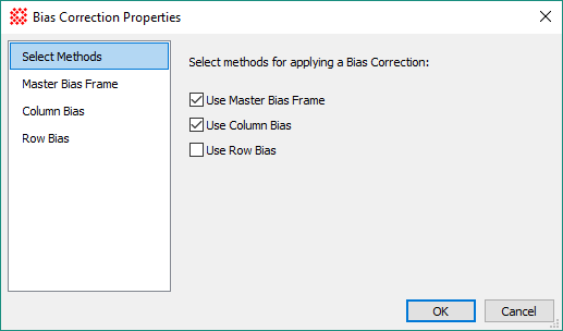
The Bias Correction Properties dialog is used by all higher level calibration procedures that create and apply image calibrations, including Create Master Bias, Express Image Calibration, and others. The pages of this dialog provide several Bias correction methods for removing CCD Bias effects from the raw CCD images, including using a Master Bias frame as well as higher order overscan, underscan, and other Bias methods. After configuring the chosen methods, select them using the checkboxes on the Select Methods page.
Select the Bias correction method(s) by checking their box on the Select Methods page. More than 1 method can be applied; for example, the Select Methods page below indicates that both a Master Bias Frame and a Column Bias correction will be applied to the raw images.
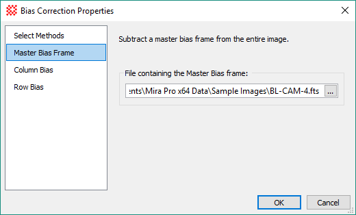
Use this method to subtract a master Bias frame from each image. The page has a single property, which selects the master Bias frame from a file. To choose a file containing the master Bias frame, click[...] and select its file.
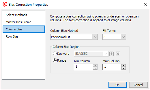
Use this method to calculate and subtract a Bias function of row position evaluated over a range of columns. The Column Bias Method property selects the type of column Bias function to be used. Other parameters control the operation of the selected method.
|
Column Bias Properties |
|
|
Column Bias Method |
Selects the method used to calculate and apply the column-direction Bias correction: The Bias is calculated in the following ways: 1. Mean Value: Calculates the mean value over the specified range of columns. 2. Median Value: Calculates the median value over the specified range of columns. 3. Polynomial Fit: Calculates a polynomial of up to 10 terms for pixels in the specified range of columns. 4. Erase Line:Reads an erase line from the image, which is a Bias column calculated at image acquisition time and stored in an image column for later use. |
|
Fit Terms |
If method 3, Polynomial Fit is selected, use this list to select the number of terms in the fit. For example, use 3 terms to fit a parabola. |
|
Column Bias Region |
Specifies the region used for the Bias calculation. If Column Bias Method = 1, 2, or 3 is selected, then a region of 1 or more columns may be selected. For method 4, the Erase Line is stored in a single column of the image array. |
|
|
This selection determines how the rows are specified for Bias measurements. Many camera controllers save the column and row limits of the Bias region as a header keyword. To use this capability, enter the name of the header keyword that holds the [column,row] endpoints of the Bias region. A typical name for this keyword is BIASSEC. |
|
Min Column |
If Keyword is not selected, this gives the minimum column number for the Bias calculation. If Column Bias Method = Erase Line, then this specifies the only column containing the Erase Line. |
|
Max Column |
If Keyword is not selected, this gives the maximum column number for the Bias calculation. |
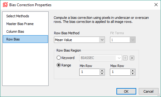
Use this method to calculate and subtract a Bias function of column position evaluated over a range of Rows. The Row Bias Method property selects the type of row Bias function to be used. Other parameters control the operation of the selected method.
|
Row Bias Properties |
|
|
Row Bias Method |
Selects the method used to calculate and apply the row-direction Bias correction: The Bias is calculated in the following ways: 1. Mean Value: Calculates the mean value over the specified range of rows. 2. Median Value: Calculates the median value over the specified range of rows. 3. Polynomial Fit: Calculates a polynomial of up to 10 terms for pixels in the specified range of rows. 4. Erase Line:Reads an erase line from the image, which is a Bias row calculated at image acquisition time and stored in an image row for later use. |
|
Fit Terms |
If method 3, Polynomial Fit is selected, use this list to select the number of terms in the fit. For example, use 3 terms to fit a parabola. |
|
Row Bias Region |
Specifies the region used for the Bias calculation. If Row Bias Method = 1, 2, or 3 is selected, then a region of 1 or more rows may be specified. For method 4, the Erase Line is stored in a single row of the image array. |
|
|
This selection determines how the rows are specified for Bias measurements. Many camera controllers save the column and row limits of the Bias region as a header keyword. To use this capability, enter the name of the header keyword that holds the [column,row] endpoints of the Bias region. A typical name for this keyword is BIASSEC. |
|
Min Row |
If Keyword is not selected, this gives the minimum row number for the Bias calculation. If Row Bias Method = Erase Line, then this specifies the only row containing the Erase Line. |
|
Max Row |
If Keyword is not selected, this gives the maximum row number for the Bias calculation. |
Mira Pro x64 User's Guide, Copyright Ⓒ 2023 Mirametrics, Inc. All
Rights Reserved.