Tutorial: Introduction to Astrometric Calibration
This tutorial shows you how to calibrate the image locations in units of celestial coordinates. Such a calibration must exist before you can measure accurate astrometric positions, distances, and angles in units of right ascension and declination. This tutorial assumes you understand how to display an image and work with an image set. Also see the Astrometric Calibration command and its sub-topics.
Astrometric calibration involves marking a number
of points and entering the celestial position for each point. When
at least 3 points are marked, you can click the ![]() button to compute the calibration, or "plate solution".
After computing the calibration, you can evaluate the quality of
the plate solution by examining the "rms error" of the equations or
the residuals (marked position minus predicted position) of the
references stars. You can change or delete points having high
residuals and re-calculate the calibration. You can also remove
points or add new reference points as desired. When you have an
acceptable solution, you may wish to save the calibration by saving
the image using one of the typical methods. In this tutorial we
will open an image, mark 6 reference points, and use them to
compute the plate solution.
button to compute the calibration, or "plate solution".
After computing the calibration, you can evaluate the quality of
the plate solution by examining the "rms error" of the equations or
the residuals (marked position minus predicted position) of the
references stars. You can change or delete points having high
residuals and re-calculate the calibration. You can also remove
points or add new reference points as desired. When you have an
acceptable solution, you may wish to save the calibration by saving
the image using one of the typical methods. In this tutorial we
will open an image, mark 6 reference points, and use them to
compute the plate solution.
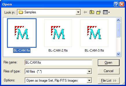
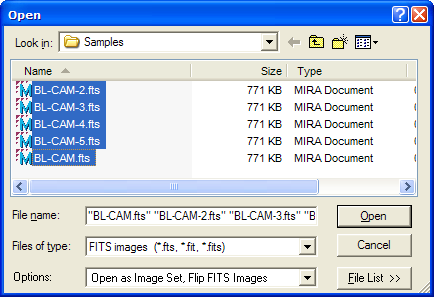
To begin, use the File > Open command to load the Open dialog. As shown below, select the sample image BL-CAM.fts and click [Open] to display it in Mira.
After opening the image, click the Image Window > Coordinates > Astrometric Calibration command in the pull-down menu. This opens the Astrometric Calibration Toolbar. As typical in Mira, the toolbar opens on the left border of the image window with marking mode active:
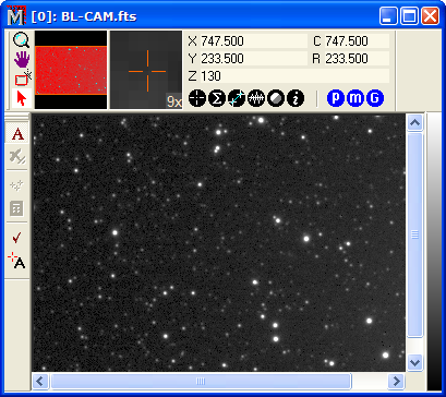
As shown above, the top toolbar button is pressed, indicating that marking mode is active. In marking mode, left clicking on the image sends a command to the astrometric calibration task. This is used to add, delete, of change reference points:
If you click on a point to add a calibration marker, this allows you to enter the celestial coordinates for that point.
If you click on an existing marker, you can delete the point or change its reference data.
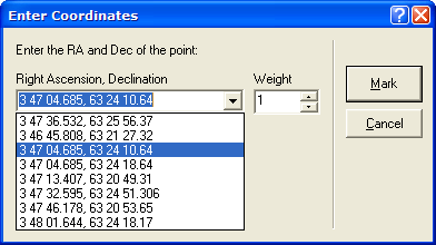
Now we will mark the first point on the image. In marking mode, notice that the mouse pointer uses a particular icon which shows you that Mira is in marking mode for astrometric calibration. Move the pointer onto the star at coordinate (620,380) and click the left mouse button to mark it. This opens the Enter Coordinates dialog as shown below:
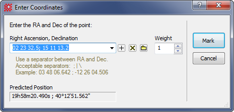
Into the Right Ascension, Declination field, type-in this position, as shown in the picture above:
3 46 45.808, 63 21 27.32
This specifies the right ascension and declination of the point just marked. The two values are separated by a comma (notice that this field uses a history list box that remembers recently entered values. Your position may be saved as recently entered value if you choose to re-mark this position now or in a future Mira session). After entering the data, click [Mark] to accept the point. The point data is displayed in the Astrometric Calibration Report window, as shown below. If you do not want to use this point, simply click [Cancel] to abort the entry and erase the marker from the image.
Notice that the image now displays a marker at the position near where you clicked. Mira computes an accurate centroid position based on your click; this gives a more accurate calibration.
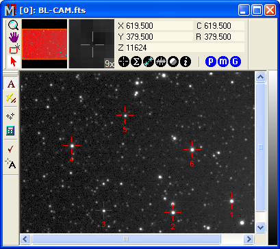
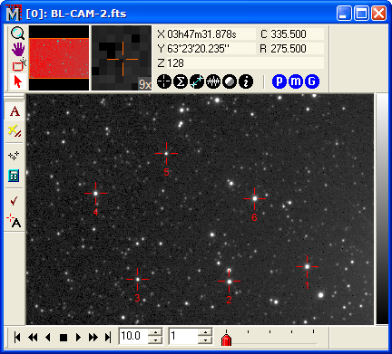
Three reference points is a minimum for computing a plate solution. However, it is usually better to mark more points, since any 3 points can be fit by a completely wrong solution and there is no way to verify the accuracy of the solution unless you use more. Using at least 4 reference points makes the solution mathematically "over-determined", which means that the extra information can be used to estimate the uncertainty in the solution and, more importantly, to detect errors in your reference data. In this exercise, we will mark 6 points. Proceed to mark the points listed below, using the following picture as a guide for which stars to mark:
point 1: 3 46 45.808, 63 21 27.32
point 2: 3 47 13.407, 63 20 49.31
point 3: 3 47 46.178, 63 20 53.65
point 4: 3 48 01.644, 63 24 18.17
point 5: 3 47 36.532, 63 25 56.37
point 6: 3 47 04.685, 63 24 13.64
After marking these 6 points, the image
window displays the markers shown in the picture below. We are now
ready to do the plate solution. Click ![]() to
compute the calibration.
to
compute the calibration.
The calibration allows the Image Bar to display coordinates in both Column and Row (C,R) and Right Ascension and Declination (X,Y) formats. You can verify this by roaming the mouse pointer around the image.
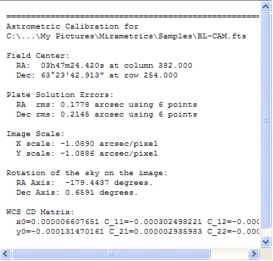
Calculating the plate solution opens the Astrometric Calibration Messages window shown below. Data in this window and in the Report window describe the calculation and results. This information can be used to evaluate the quality of the calibration. First, let's look at the Message window:
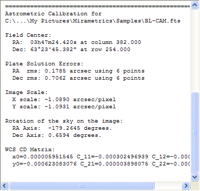
As you can see in the Message Pane, the plate solution tells you about the image, including its center coordinates, rotation, and image scale, and the plate solution errors. The Plate Solution errors give the random uncertainty of the calibration in both Right Ascension (RA) and Declination (Dec). Any position you measure in the image will have a 1-sigma uncertainty of this amount (1-sigma means that there is a 68% probability that the correct position is within this distance of the position predicted by the astrometric calibration). Looking at the values, we have a right ascension uncertainty of 0.18 arcseconds and a declination uncertainty of 0.7 arcseconds. With a maximum RMS uncertainty of 0.7 arcseconds, that's not too bad a solution, so we are finished with the calibration.
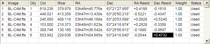
Are we really finished with the calibration? First, notice that the declination uncertainty is quite a bit larger than the Right ascension uncertainty. Furthermore, 0.7 arcseconds is rather large. Typically you should be getting RMS calibration errors smaller than about 0.3 to 0.4 arcseconds in both directions. This begs the question whether one or more of the calibration stars is "bad" and should be removed from the plate solution. Let's examine the X and Y residuals in the Report window and see if they tell us anything. A star with an erroneous coordinate will have a high residual. Here is the Report window:
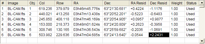
Note that the Dec Residual column is highlighted for star 6. It has the highest residual (highlighted in black), which means that the plate solution was able to fit the other 5 stars better, so it ends up with a great difference between the predicted position and actual position—in other words, a higher residual. It turns out that the wrong position was entered for the declination of star number 6. In actuality, the declination should be "63 24 10.640", not "63 24 13.640". We need to change this position and re-calculate the plate solution. To do this, right click on the row that lists the star having the high residual. This opens the menu shown below.
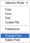
In the menu, select the Change Point command to open the Change Point Data dialog shown below. You can also open the Change dialog by activating Marking mode, then clicking on the marker you wish to change.
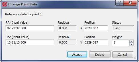
Click on the Declination field and change the
13.640 to 10.640. Then click [Accept]. This closes the dialog (if you wish to
change other points, repeat this procedure and enter the correct
data, or use the [Delete] menu
command or dialog button to remove the star from the calibration
altogether). After deleting the point, click ![]() to re-compute the calibration. The results looks like
this:
to re-compute the calibration. The results looks like
this:
As you can see, correcting the declination we entered for point 6 has reduced its residual from +2.2431 arcseconds to +0.4732 arcseconds. All points now have residuals that are similar to each other, so we accept this calibration. You an see all the residuals in the Report window as shown below.
Since there is no point with a residual that is far larger than the others, there is no clearly bad point used in the plate solution. Looking at the Messages window, you can also see that the image scale and field rotation values are similar for both axes. They should be close but will not necessarily agree because of statistical errors in the reference positions. This calibration is acceptable.
All of the plate solution values are automatically converted to a standard WCS protocol and saved in the image header. Roam the image cursor around the image and you can see that the X and Y values read out directly in right ascension and declination. To permanently save the astrometric calibration, save the image using File > Save or an equivalent command. Be sure to save the image in FITS format, since only FITS can save a WCS coordinate calibration.
Let's extend the lesson of the previous section to calibrating an image set in which the images are misaligned by only 5 to 10 pixels at most. This procedure is useful, for example, when acquiring a series of images that are drifting a small amount from one frame to the next. The main change in the procedure we just followed will be to mark the points on one image and then track those points onto the other images. This allows all the calibrations to be done at once (for more information on displaying and working with an image set, see the tutorial Tutorial: Displaying an Image Set).
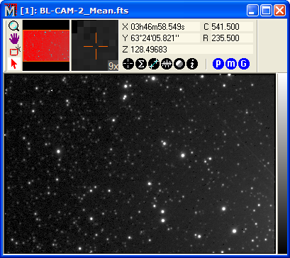
Begin by opening the series of images as an image set in a single window. To do this, use File > Open to open all the BL-CAM sample images in the folder "<Documents>\Mira Pro x64\Sample Data".. As shown below, select all five BL-CAM images using the Windows Ctrl/Shift + Click strategy. Also be sure the Open as Image Set option is checked in the Options box at the bottom of the Open dialog. The selected images should appear like this:
After opening the 5 BL-CAM images as an image set. click the Image Window > Coordinates > Astrometric Calibration command to open the toolbar. The Image Window containing the 5 images should look like that shown below (note that we have used the View > Cursor > Hide command to remove the image cursor from the window).
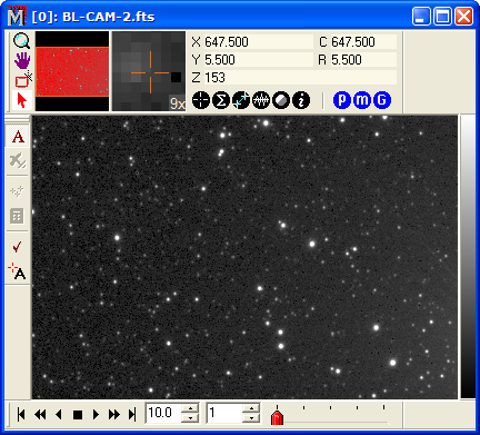
Examine the members of the image set: Using the red scrollbar thumb on the Animation Bar, scroll through the image set. You will see that the images are gradually drifting relative to each other.
Next, you need to mark the same 6 reference points on the BL-CAM image; after that we will compute the calibration of that image, and finally transfer the reference points onto the other images. If the BL-CAM image is not loaded first on the stack, then you can either switch to it or use the Image Set Properties (Ctrl+I) command to move it to the top. Mira does not care which if the images is used as the reference. Marking the 6 points on the BL-CAM image is aided by the fact that you already marked them once, so their coordinates are in the history list of the Enter Coordinates dialog. You do not have to re-mark the BL-CAM image, but if you saved after calibration, then using it will make the point marking go faster this time. The picture below shows the Enter Coordinates dialog with coordinates being selected from its history list.
When you are finished marking all 6 points, the image window looks like this:
Now click ![]() to calculate the
calibration for the image where the reference points are marked.
Now we use this to calibrate all the remaining images: Click the
to calculate the
calibration for the image where the reference points are marked.
Now we use this to calibrate all the remaining images: Click the
![]() button on the toolbar to track the points into
all other images. Mira will compute the plate solutions for all
images if the following 2 conditions are met:
button on the toolbar to track the points into
all other images. Mira will compute the plate solutions for all
images if the following 2 conditions are met:
The Auto Update box is checked in the Other Properties dialog. This makes Mira automatically calibrate after tracking.
The ![]() button (Process
Image Set) is in image set mode (colored blue). This makes the
auto-calibration apply to the entire image set.
button (Process
Image Set) is in image set mode (colored blue). This makes the
auto-calibration apply to the entire image set.
Otherwise, you can force a calibration of one image
or the entire image set by clicking the ![]() button.
Examine the plate solution results in the Message window and look
at the residuals in the Report window. If you are satisfied with
the solutions, you are done with astrometric calibration for the
image set.
button.
Examine the plate solution results in the Message window and look
at the residuals in the Report window. If you are satisfied with
the solutions, you are done with astrometric calibration for the
image set.
Finally, let us add two additional steps to work with the image set we just calibrated. If an astrometric calibration exists, you can use this to register the image set. Do this using the Image Window > Coordinates > Align by WCS command. The astrometric calibration is saved in the image headers using the WCS protocol, so it is used to map each point in all images onto the same pint in the top image. After the Align by WCS command finishes, scroll through the image set to examine the alignment. It should be very accurate—if not, then some misidentified points were added by the tracking process. You should be able to tell which ones by looking at the residuals. But the images should be well aligned, which brings us to the next step.
Next, use the Process > Math > Combine Image Set command to combine the registered image set by the Mean value. This will average together all the images, exposing any misalignments as elongation in the combined stars. The result appears in a new window that looks like this:
Now magnify the image about the point (308,131). Since no toolbar command mode is active, you can click on the image to give it the mouse focus. That allows you to use its thumb wheel to magnify up and down. Move the pointer onto the star at column,row coordinate (308,131) and rotate the thumb wheel forward to magnify to the maximum of 16x. The result looks like this:
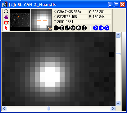
In the picture above, the combined star image is quite round, indicating that the images were very well registered using the WCS resulting from the astrometric calibration.
Astrometric Calibration Results
Mira Pro x64 User's Guide, Copyright Ⓒ 2023 Mirametrics, Inc. All
Rights Reserved.